DIY Smart Water Meter: Monitoring Water Consumption with LoRaWAN and an Inductive Sensor
I wanted to track my water consumption with more detail than a yearly bill provides. This project uses a TL-W5MC1 inductive proximity sensor, a LoRaWAN microcontroller, and a circular buffer algorithm to monitor water usage with minute-level accuracy.
The full source code is available on GitHub.
Why Build This?
A standard water meter shows a cumulative total. But I wanted answers to questions like:
- When do I use the most water?
- How much does a shower actually consume?
- Is something leaking at night?
The system needed to:
- Detect each liter passing through the meter
- Store consumption data with fine granularity
- Transmit wirelessly over long distances
- Handle power outages without losing the meter index
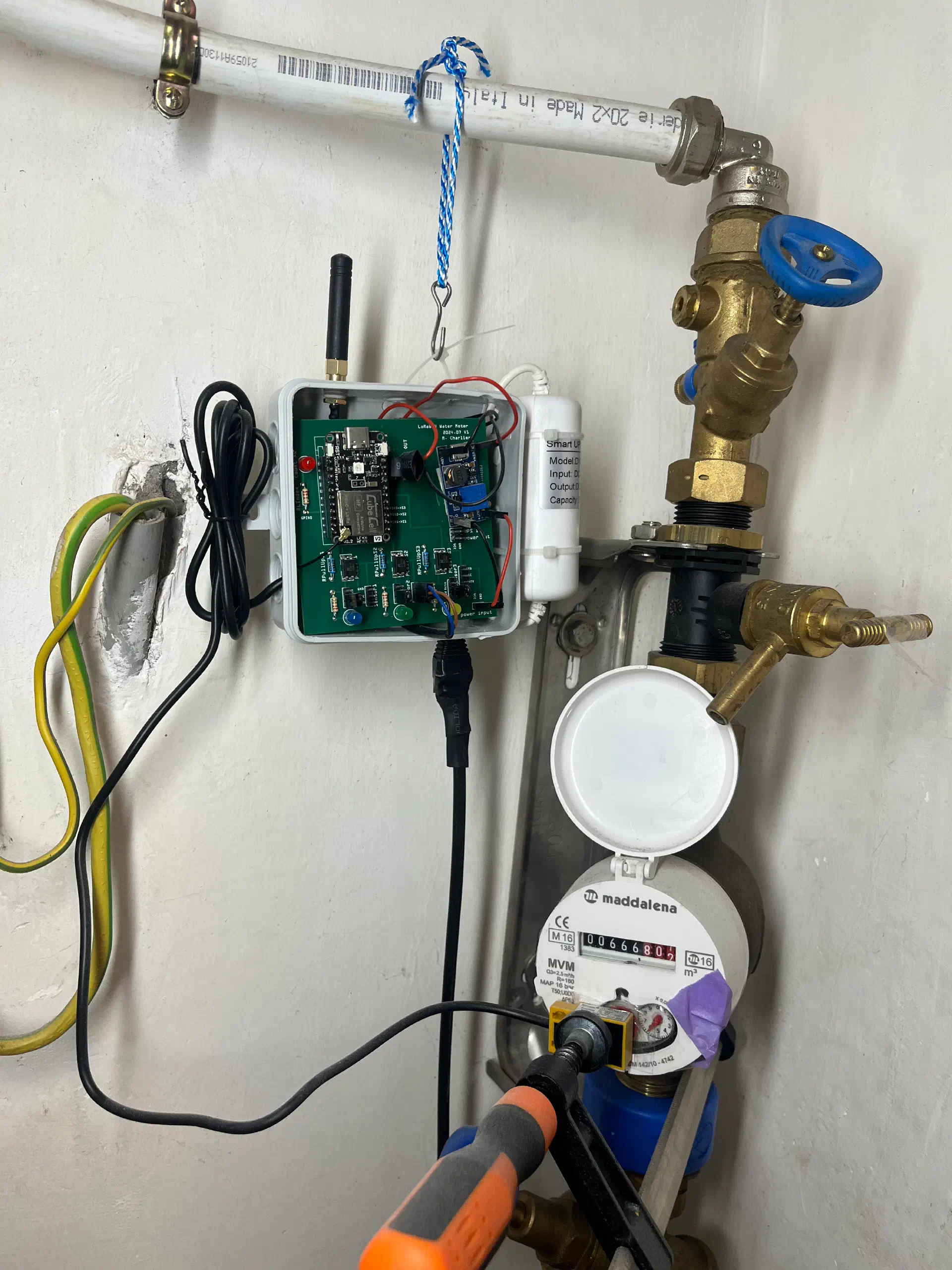
Hardware
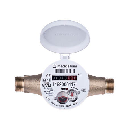
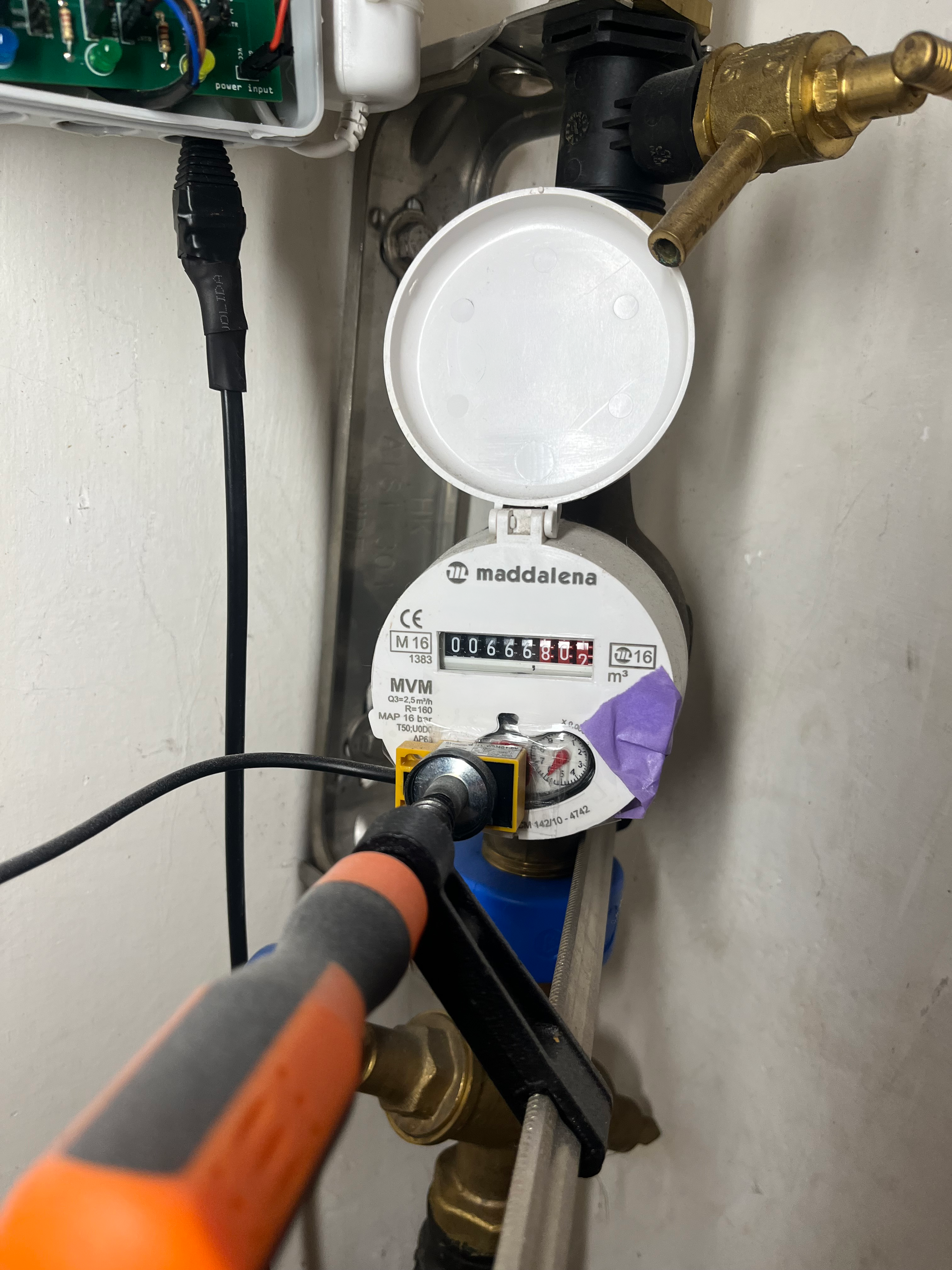
Water Meter
My water meter is a Maddalena MVM. It has a rotating dial with a steel element that completes one rotation per liter, which makes it compatible with an inductive proximity sensor.
Sensor compatibility: Before choosing a sensor, check your water meter carefully. The rotating disc can be made of steel, aluminium, or it can use a magnet. Each material requires a different detection technology. The TL-W5MC1 works on steel discs only. For aluminium discs, you need a different inductive sensor (such as the LJ18A3-8-Z/). For magnetic discs, a reed switch or Hall effect sensor is the right tool. The wrong sensor will simply never trigger.
Sensor: TL-W5MC1 Inductive Proximity Sensor
The TL-W5MC1 is an NPN inductive proximity sensor that detects metal without contact. Positioning the sensor above the steel dial lets us count each rotation.
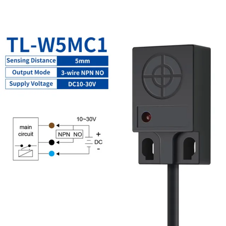
Wiring:
- Brown, V+ (10-30V)
- Black, digital output (to optocoupler input)
- Blue, GND
The sensor outputs LOW when metal is detected and HIGH otherwise, creating one pulse per liter.
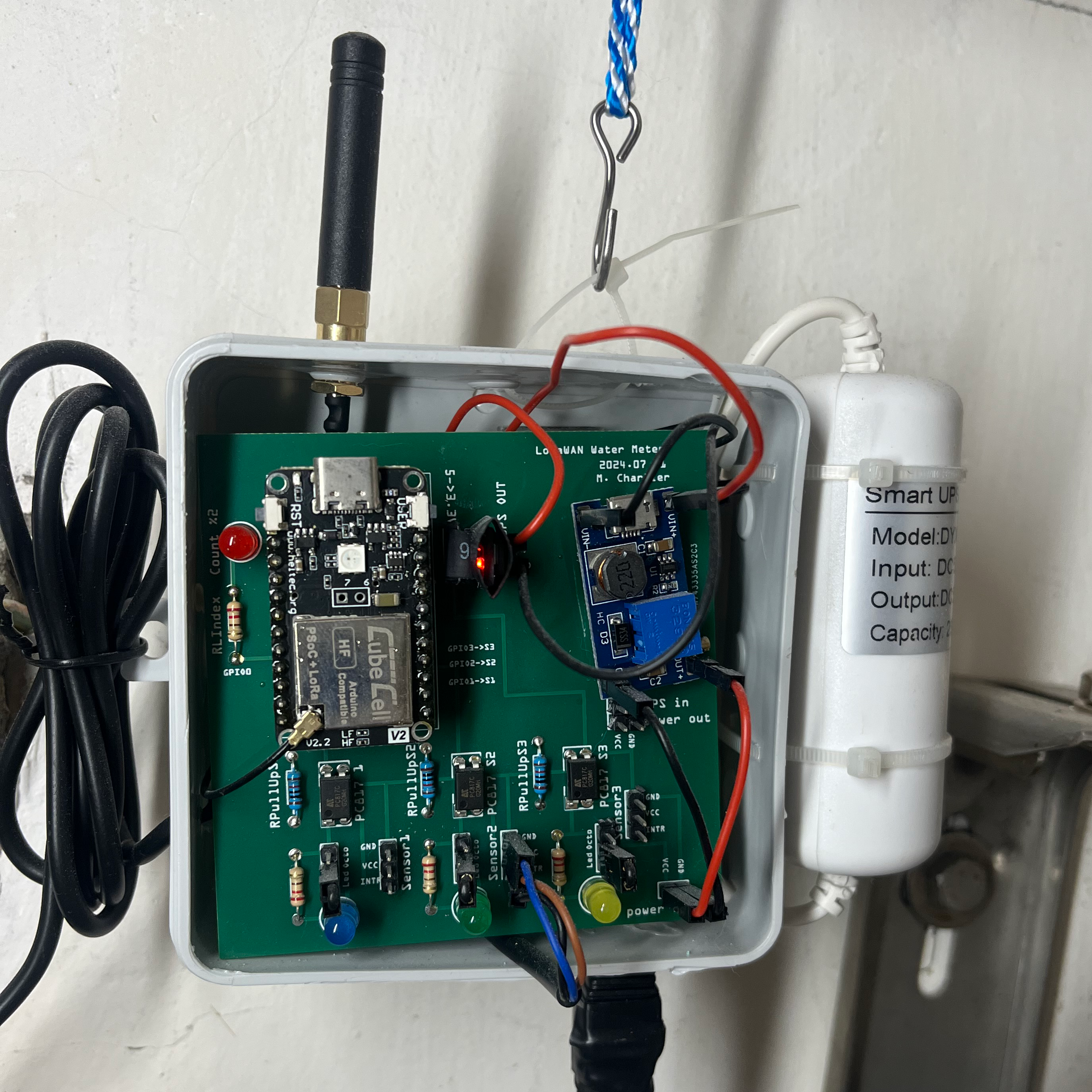
Microcontroller: Heltec CubeCell
I went with a Heltec CubeCell for its built-in LoRaWAN support, low power consumption, and small size. The version I use has an external antenna connector, which improves range significantly compared to PCB antennas: useful when the water meter is in a basement or utility room.
LoRaWAN easily covers 100+ meters through walls and floors, making this setup practical for multi-story buildings. The water meter can be several floors away from the gateway without connectivity issues.
Power Supply Architecture
The TL-W5MC1 requires 10-30V input, so battery power was not practical. I had a 5V transformer available near the water meter, which led to this power architecture:
5V Transformer (from wall outlet)
    |
    +---> Voltage Step-Up (5V -> 12V) ---> TL-W5MC1 Sensor
    |
    +---> Mini UPS (5V, designed for USB cameras)
              |
              +---> Voltage Converter (5V -> 3.3V) ---> CubeCell Arduino
Why the UPS? Power outages happen. Without backup power, the microcontroller would reset and lose the current water meter index. The small USB camera UPS keeps the system running through brief outages, preserving the count.
Isolation with Optocoupler: The sensor runs at 12V while the Arduino operates at 3.3V. An optocoupler isolates these two circuits, protecting the microcontroller from voltage spikes and providing clean signal separation.
PCB Design
I designed the PCB using Fritzing, a straightforward tool that works well for simple boards like this. PCBWay manufactured the final PCB.
Full Installation

Software
Pulse Detection with Debouncing
Water meter dials do not produce clean signals. The metallic element passes under the sensor gradually, which can cause false triggers. The code uses debouncing to handle this:
| |
Both rising and falling edges are tracked, requiring a stable signal for 100ms before counting a pulse.
Circular Buffer for Minute-Level Accuracy
Rather than storing every timestamp, I use a circular buffer with two parallel arrays:
| |
The logic:
- Every minute, check if the pulse count changed
- If unchanged: increment the interval counter (max 60 minutes)
- If changed: move to the next buffer slot and record the new count
This compression works well for varying consumption patterns:
- During low/no usage (night), one entry can represent up to 60 minutes
- During active usage, each minute gets its own entry
- 50 slots can store anywhere from 50 minutes to 50+ hours of history
The buffer also handles network interruptions gracefully. My wife turns off the LoRaWAN gateway every night (she does not want to see the blue lights blinking), so the sensor cannot transmit for several hours. No data is lost: the circular buffer keeps accumulating history until the gateway comes back online, then the next transmission includes all the missed data.
| |
LoRaWAN Transmission
Data transmits hourly via LoRaWAN. The frame format:
| Byte | Content |
|---|---|
| 0 | Frame version (3 bits) + User button flag (1 bit) + Interval minutes (4 bits) |
| 1 | Transmission counter |
| 2-5 | Current pulse count (32-bit, LSB first) |
| 6+ | History pairs: [interval_count, pulse_LSB] for each entry |
The backend can reconstruct the complete consumption timeline from this data.
Power Management
Between transmissions, the device sleeps. It wakes every minute to check for pulses and update history, then returns to sleep:
| |
Remote Configuration
The meter reading can be set remotely via LoRaWAN downlink:
| |
Three modes:
- Mode 0: Set current count only
- Mode 1: Offset all history entries
- Mode 2: Reset history completely
What I Learned
After running this for several months:
- I can see daily consumption patterns clearly
- Different activities (showers, laundry, dishwasher) show distinct signatures
- Caught a running toilet that was wasting water
- Seasonal usage variations are now visible
The full source code, including the PCB design files, is available on GitHub.
Moving to a new house brought new challenges: a different water meter disc material requiring a sensor swap, and water tanks that needed their own monitoring. Two follow-up posts cover those adaptations: one on choosing the right inductive sensor for your water meter, and one on monitoring water tanks with a LoRaWAN pressure sensor.
Comments